

PLASTIC ELEMENTS & COMPONENTS
Kirkholm works with both large and small plastic elements or components in our projects. Therefore, we know that both the material and the processes are different and contain a different complexity than when we work with other materials, such as steel. Here, we describe this complexity with a focus on both design, material selection, casting process and calculation based on a actual problem that one our customers experienced.
DESIGN OF LARGE PLASTIC ITEMS
PROBLEM
A customer in the agricultural and food sector had challenges with both the physical shape and strength of a plastic item for storing liquid at 50°C over a longer period.
Kirkholm was contacted to analyze the challenges of the existing subject and, subsequently, come up with proposals for changes in collaboration with the customer to address challenges in terms of strength and creep, meaning changes in the physical form under prolonged stress.
INITIAL ANALYSIS OF THE CHALLENGES
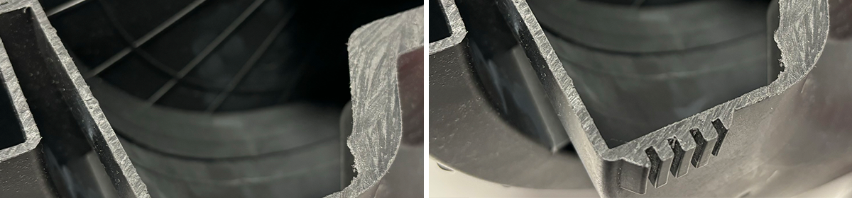
After a visit to the customer, we analyzed their existing 3D models and the casted element that came out of the molds via a few preliminary FEM calculations.
This was carried out to clarify the problems of the current structural plastic elements, where test castings, with few different types of fiber reinforced plastic, had already been made in the new mold.
It can often be difficult to get specific information about the composition of different plastic materials provided by different suppliers. Creep curves are in particular often difficult to find for the specific environment to which the plastic item is exposed. Therefore, the work began with theoretical knowledge, testing of materials and curves on plastic materials from various suppliers. These analyses and calculations were carried out in order to create a strong basis for further work on the project.
SHRINKAGE AND CASTING PROCESS
Plastic parts have a number of parameters that influence the geometry and strength of the finished item, and therefore it is not possible to assess the strength of the plastic part by only examining a 3D model. The parameters below often influence on the geometry and strength of the finished item:
- Material selection
- Filling percentage - fiber etc.
- Flow direction
- After pressure - time and pressure
- Filling pressure and filling speed
- Mold temperature
- Melting temperature
- Geometry - mold-bound/non-mold-bound
Via a Moldflow analysis of a mold, you can help predict how a plastic element will behave when it comes out of a specific mold. All the parameters that can be changed in the injection molding process can be simulated in a Moldflow analysis. This gives the opportunity to work with all these parameters right at the start of the design process - hopefully before milling an expensive mold.
When choosing the plastic material to be used for a part, you look at how much it contracts when the part cools down in the injection mold. It could, for example, be 0.7%. When you mill a mold for injection molding, the mold is scaled in relation to this, so that you get the desired dimensions of the finished plastic part. However, the work with shrinkage is not limited to this.
If there is a difference in the amount of material in the bottom and sides of a box, it will create residual stresses and warpage on the workpiece when the material contracts - and straight edges in a 3D design will be curved when they come out of the injection mold. If you adjust e.g. on the location of the injection nozzles, a more continuous movement can be achieved while filling the mold during injection molding. This can help to ensure a uniform fiber orientation, whereby you get the strongest item with a more uniform shrinkage.
The residual pressure in the casting process can also be a significant factor in ensuring uniform shrinkage. Here we asked the customer to speak to the manufacturer of the injection mold, as we saw a number of challenges in relation to overprinting and shrinkage. The residual pressure in the structural plastic item is relevant to how the shrinkage occurs, as Carsten Kragh, Sr. Mechanical Designer mentions
"When transitioning from injection pressure to holding pressure in molding,
it is crucial to establish the holding pressure before the gate freezes."
For the specific plastic item, the work on the process was carried out in close collaboration with the customer, the company that will be manufacturing the items and Kirkholm, in order to find which parameters should be focused on to ensure the achievement of the desired item.
FINITE ELEMENT ANALYSIS (FEA), LOAD SCENARIOS AND CRYBRATION
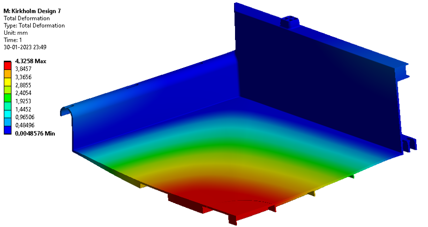
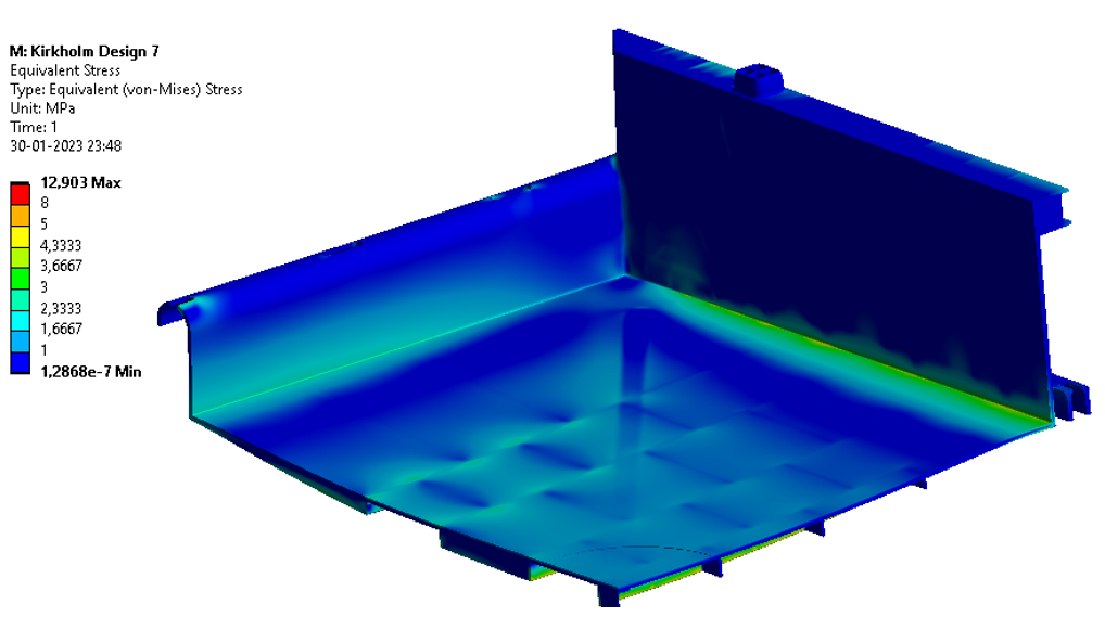
The FE analysis of the structural plastic part was divided into two load scenarios: storage of liquid and stacking of 16 pcs. on top of each other. In both cases, the structural strength is challenged by the elevated temperature of 50 °C.
Kirkholm performed several FE analysis in relation to stress and deformation. Here, the simulations showed that the strength was not sufficient for the plastic material used in the existing design. In close collaboration with the customer, Kirkholm carried out a series of design iterations with subsequent structural analysis of the plastic container, where we always took into account the various casting technical parameters in all our changes.
In both loading scenarios, creep was a dimensioning factor, as the deformation of polymers will increase with time under constant loading. Creep is 3-dimensional, as the degree of deformation depends on temperature, load and duration of the load, which is why you analyze and calculate on different stress and strain diagrams.
In this context, we performed FE analyses on the plastic element with different types of fiber-reinforced plastic materials.
When working with large plastic items that are subject to creep, it is common to use a chord height on the item. The chord height helps reduce tension in the workpiece and, consequently, the tendency to creep. In this case, the chord height of the plastic blank was problematic, as the final plastic blank had different dimensions than the nominal model, resulting in a bulge in the middle. This bulge was not beneficial for achieving the desired capacity in the boxes.
💡 "Chord height" is the term for the height of a bow from where it rests to where the bow is at its highest point. Beams and concrete structures are produced with "Chord height" to counteract the deflection that normal loading would otherwise cause.
PROPOSED SOLUTION
The final solution was created in close cooperation between the customer, Kirkholm and the injection mold technician, as it is an expensive process to change the workpiece and the mold.
Our final delivery consisted of the following results, which the customer could continue to work with:
- A new design which reduced the deflection in the middle of the box by 20%
- Demonstration of the strength of the design based on FEA simulations
- A series of improvement measures to increase the strength of the item
- Linear and non-linear analyses
- A buckling analysis
- FE analyses and calculations in ANSYS
If you have questions about plastics or would like to know more about how Kirkholm works with plastics and FEA, then have a chat with have a chat with our CSO and partner about the possibilities: